BMW Front Electronic Module (FEM)
The Front Electronic Module (FEM) represents a new generation which supersedes existing control units and their functions. As a result of the modular principle, the Front Electronic Module (FEM) can be installed in all series. The Front Electronic Module (FEM) is the central control unit in the vehicle electrical system. At the same time, the Front Electronic Module (FEM) is the gateway for the other control units. The Front Electronic Module (FEM) provides functions from the previous control units footwell module (FRM), Car Access System (CAS), Junction Box Electronics (JBE) and central gateway module (ZGM).
The central gateway module (ZGM) is installed in the Front Electronic Module (FEM) as an independent control unit. The aim is to reduce the number of control units and improve component networking. At the same time, the optimization of the wiring harness reduces the physical bus capacity.
Functional description
The following functions of the Car Access System (CAS) have been integrated in the Front Electronic Module (FEM)
- Terminal control
- Electronic immobilizer
- Comfort Access
- Electric steering lock
- Central locking system
The following functions of the Junction Box Electronics (JBE) have been integrated in the Front Electronic Module (FEM)
- Power window regulator
- Wash/wipe system
- Washer jet heating
- Climate control
- Seat heating
- Mirror heating
- Automatic air re circulation control
- Rain-light-solar-condensation sensor
The following functions of the footwell module (FRM) have been integrated in the Front Electronic Module (FEM).
- Exterior lighting
- Brake light
- Interior lighting
- Exterior mirrors
The central gateway module (ZGM) is integrated in the Front Electronic Module (FEM). It is seen as a control unit within the control unit, as the central gateway module (ZGM) acts as a self-sufficient control unit within the Front Electronic Module {FEM).
The task of the central gateway module (ZGM) is to connect all bus systems. This combination allows general use of information from the individual bus systems. The central gateway module (ZGM) is able to implement various reports and speeds on other bus systems. The programming data are transferred to the vehicle by Ethernet via the central gateway module (ZGM).
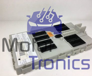
The Front Electronic Module (FEM) is located in the A-pillar of the passenger footwell and controls all functions in the front section of the vehicle.
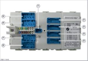
| Item | Explanation | Item | Explanation |
| 1 | 12‐pin plug connection | 2 | 54‐pin plug connection |
| 3 | 54‐pin plug connection | 4 | 54‐pin plug connection |
| 5 | 54‐pin plug connection | 6 | 42‐pin plug connection |
| 7 | 54‐pin plug connection | 8 | 54‐pin plug connection |
| 9 | 42‐pin plug connection |
Structure and inner electrical connection
The front electronic module (FEM) is connected to the vehicle with 9 plug connections. To avoid confusion during connection, connector housings of the same colour have different encoding. This prevents them being inserted in the wrong position inadvertently. The input for the voltage supply of the FEM is a 1-pin plug connection.
Fuses for the following consumer units are installed in the fuse block of the Front Electronic Module (FEM):
- Central locking drive
- Outside door handle electronics
- Power-train of the power window regulators
- Light operating facility, operating facility for the assist systems and steering column switch cluster
- Rear Electronic Module (REM) and headlight driver module
- Fanfare
The following graphic shows the fuse arrangement of the Front Electronic Module (FEM)
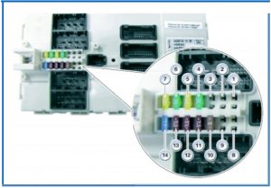
| Item | Explanation | Item | Explanation |
| 1 | F1: Reserved (not used) | 2 | F2: Reserved (not used) |
| 3 | F3: Reserved (not used) | 4 | F4: Power window regulator, Front passenger door |
| 5 | F5: Central Locking System | 6 | F6: Power window regulator, driver’s door |
| 7 | F5: Central Locking System | 8 | F8: Reserved (not used) |
| 9 | F9: Reserved (not used) | 10 | F10: Lights, assist, steering column switch cluster |
| 11 | F11: Rear Electric Module (REM) and headlight driver module | 12 | F12: Standard heating and air conditioning, Dynamic Stability Control (DSC) and OBD |
| 13 | F13: Outside door handle electronics, contact-free tailgate opening and Combox and analysis | 14 | F14: Fanfare |
System functions
The following system functions of the Front Electronic Module (FEM) are described:
- Gateway
- Terminal control
- Central locking system
- Electronic immobiliser
- Alarm system
- Comfort Access
- Contact-free tailgate opening
- Steering column adjustment
- Power window regulator
- Slide/tilt sunroof
- Exterior lighting
- Interior lighting
- Wipe and wash
- Heating and climate control
- Electrical exterior mirrors
- Electrically adjustable seats
- Periphery functions
- Vehicle setting
- Check Control
System network
The following graphic (functional wiring diagram) shows the system network for the Front Electronic Module (FEM). The Front Electronic Module (FEM) acts as transmitter and receiver. The signals are assigned internally to the corresponding receivers and output.
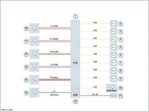
| Item | Explanation | Item | Explanation |
| 1 | Front Electronic Module (FEM) | 2 | LIN: Electric steering lock |
| 3 | LIN: Steering column switch cluster | 4 | LIN: Rain-light-solar-condensation sensor, roof function center and inside mirror |
| 5 | LIN: Multi function steering wheel | 6 | LIN: Driver’s seat operating facility and light operating facility |
| 7 | LIN: Exterior mirror and contact free tailgate opening | 8 | LIN: Headlight driver module |
| 9 | LIN: Remote control receiver | 10 | LIN: Wake-up line for DME (Digital Engine Electronics) or DDE (Digital Diesel Electronics) |
| 11 | Terminal 30: Outside door handle electronics | 12 | Central gateway module (ZGW) integrated as module in front electronics module (FEM) |
| 13 | Ethernet: Headunit, instrument cluster, CBX-MEDIA, CBX-ECALL and audio amplifier | 14 | FlexRay: Dynamic stability control (DSC), Integrated chassis management (ICM) Vertical Dynamics Management (VDM), electromechanical power steering and control unit for all-around camera vision camera (TRSVC) |
| 15 | D-CAN: Diagnostic socket | 16 | Powertrain CAN: Digital Engine Electronics (DME) or Digital Diesel Electronics (DDE), Crash Safety Module (ACSM), camera-based driver support systems, fuel pump control module (EKPS), electronic transmission control (EGS), gear selector switch (GWS), REMAFA and REMABF |
| 17 | K-CAN2: Rear Electronic Module (REM), roof function centre (FZD), Parking Manoeuvring Assistant (PMA) and high-beam assistant (FLA) | 18 | Body CAN: Driver’s seat module (SMFA), front passenger seat module (SMBF), trailer module (AHM), IHKA and controller (CON) |
Gateway
The central gateway module (ZGM), which is integrated in the Front Electronic Module (FEM) carries out vehicle-internal distribution of the messages to the various data buses. The messages are forwarded to the headunit via K-CAN2. The headunit then distributes them on the Media Oriented System Transport.
Within the system network,the control units involved communicate via the following bus systems:
- The Media Oriented System Transport (MOST) uses optical fibres for data transfer. Data transfer is only possible in one direction. Data exchange is performed via the central gateway module (ZGM).
- FlexRay is employed as the bus system for networking of dynamic handling control systems and engine control. The central gateway module (ZGM), which is integrated in the new Front Electronic Module (FEM), contains a so-called star coupler with 4 bus drivers. The bus drivers pass the data on to the central gateway module (ZGM). The FlexRay control units are connected to these bus drivers. To avoid reflection on the lines, terminating resistors are fitted on both ends. FlexRay has a very high data transfer rate (10 MBit/s) and allows data exchange between the control units at a stipulated time.
- The K-CAN (body CAN) is responsible for control unit communication at low data transfer rates (100 kBit/s). The K-CAN is also linked to the other bus systems via the central gateway module (ZGM).
- The K-CAN2 (body CAN 2) is responsible for control unit communication at high data transfer rates (500 kBit/s). The K-CAN2 is also linked with the other bus systems via the central gateway module (ZGM).
- The PT-CAN (powertrain CAN) connects the engine control with the transmission control unit, and also the safety system with the assist systems.
- The PT-CAN2 (powertrain CAN 2) creates a redundancy to the Powertrain Controller Area Network (PT-CAN) in the area of the engine control and transmission control unit. The PT-CAN2 has a data transfer rate of 500 kBit/s and is equipped with an additional wake-up line.
- The LIN (local interconnect network) is mainly used in a master and slave combination.The local interconnect network bus ensures fast and reliable communication between the control units within a functional group.
- The Ethernet is a vendor-neutral, cable-based technology for the connection of networks. As a result of the Ethernet’s very high data transfer rate (100 MBit/s), the interface via the MOST bus of the central gateway module (ZGM) in the Front Electronic Module (FEM) was no longer required. Due to the high data volumes, programming of the MOST network is carried out via the Ethernet and the headunit. The headunit performs distribution on the MOST. Vehicle diagnosis messages are transmitted to the headunit via K-CAN2. Manipulation or modification of the encoding data is no longer easily possible.
Terminal control
The Front Electronic Module (FEM) assumes a central function in terminal control. The terminal control activates and deactivates terminal 30F, terminal 308 and terminal 15N for voltage supply to the control units and components. In addition, the Front Electronic Module (FEM) controls terminal 50 for activation of the starter motor and terminal 15 for end of engine running.
The Front Electronic Module (FEM) controls the following functions:
- Operating logic
- Logic gate to the consumers
- Start function
- Automatic engine start-stop functions
- System functions
After successful identification of the ID transmitter, the signals of the brake light switch and the clutch switch are read in. The corresponding signals control the activation and deactivation of vehicle functions and allow communication in the vehicle electrical system. In addition,terminal changes can be performed via operation of the START-STOP button or via diagnosis.
Central locking system
In vehicles with software version ISTA/P 2.47.1 or later:
When the 3rd remote control button, “open tailgate”, is operated, it is not only the tailgate that unlocks; all the doors on the vehicle are unlocked too.
This function change has been introduced to reduce the risk of accidentally locking the remote key in the luggage compartment.
For all vehicles in which the configurability via the headunit is not available:
With ISTA/P the assignment of the 3rd remote control button can be changed with a conversion.
Access control from the existing Car Access System (CAS) is fully integrated in the Front Electronic Module (FEM). Mechanical access to the vehicle is limited to opening of the driver’s door lock. Activation of the central locking system is carried out via identification of the ID transmitter via the rear window aerial. The remote control receiver forwards the signal to the Front Electronic Module (FEM). After a successful signal check, the Front Electronic Module (FEM) initiates activation of the central locking system. The Front Electronic Module (FEM) evaluates the status of all door contacts. This prevents, for example, the vehicle from being locked if the driver’s door is open. The Front Electronic Module (FEM) also evaluates the status of the central locking button.
Depending on its status, the Front Electronic Module (FEM) activates the central locking system.
The Front Electronic Module (FEM) controls the coordinated unlocking, locking and deadlocking of the connected doors and flaps.
- Driver’s door
- Front passenger door
- Driver’s side door, rear
- Passenger’s side door, rear
- Tailgate
- Rear window
- Fuel filler flap
- Glove box
Electronic immobilizer
There are some changes to the start enable via the electronic immobilizer. One new feature is the discontinuation of the Car Access System (CAS) signal. Powertrain CAN and FlexRay already render data transfer between Front Electronic Module (FEM) and engine control redundant. In addition, the Front Electronic Module (FEM) controls the release of the electric steering lock.
Alarm system
The alarm system (DWA) is equipped with an ultrasonic interior movement detector for monitoring of the passenger compartment. The ultrasonic interior movement detector is fully integrated in the roof function centre (FZD).
The Front Electronic Module (FEM) controls the alarm system as follows:
- The door contacts are monitored by the Front Electronic Module (FEM). If the status of a hall effect sensor changes, the change is transmitted to the ultrasonic interior movement detector via the K-CAN2. The alarm is triggered by the emergency power siren if the alarm system (DWA) is activated.
- The Front Electronic Module (FEM) also monitors the engine compartment lid contact switch. The DWA alarm is triggered as soon as the status changes.
- The Rear Electronic Module (REM) monitors opening of the tailgate.
Comfort Access
There is no longer an insertion slot for the ID transmitter in the standard equipment. The vehicle can be started without using the ID transmitter. However, operation of the ID transmitter is still required for access to the vehicle. There is an extended function as optional equipment (option 322). This extended function permits access to the vehicle without operation of the ID transmitter. In this case, the outside door handle electronics and the rear lid button allow access to the vehicle.
Depending on the vehicle equipment, all side windows, the slide/tilt sunroof and the soft top on convertibles can be closed or opened with the convenience function before getting into or after getting out of the vehicle. The convenient opening or convenient closing function can be carried out via the ID transmitter. Opening or closing of the side windows, the slide/tilt sunroof or the soft top is performed. With the optional equipment, the closing action can also be triggered by touching the outer door handles. The ID transmitter must be located on the outside, near the corresponding operating point. The ID transmitter must be detected and authenticated by the vehicle.
In the convenience function, the following components are activated in succession:
- Front power window regulator
- Rear power window regulator
- Slide/tilt roof
Contact-free tailgate opening
Contact-free tailgate opening is only available in conjunction with the optional equipment (option 322). This extended Comfort Access allows the driver to unlock, lock and deadlock the vehicle without actively using the ignition key.
With contact-free tailgate opening, the tailgate on a closed vehicle can be opened by a targeted movement of the foot (moving the foot towards the bumper and then back) near the rear bumper panel. The ID transmitter must be located on the outside, near the corresponding operating point. The ID transmitter must be detected and authenticated by the vehicle.
Steering column adjustment
Electrical steering column adjustment is controlled by the Front Electronic Module (FEM) in the following situations:
- In the case of manual steering column adjustment, the driver’s choice is read in by the steering column switch cluster (SZL) and transmitted to the Front Electronic Module (FEM) via the local interconnect network bus. The Front Electronic Module (FEM) processes the data and transmits the activation command to the steering column adjustment via a local interconnect network bus. The steering column adjustment drives the electrical steering column with 2 direct current motors. One direct current motor adjusts the steering column vertically and the other direct current motor adjusts it axially.
- In addition to manual adjustment, it is also possible to activate the electrical steering column via the memory function. The memory function is operated via the seat module. The seat module transmits the status of an activated memory button to the Front Electronic Module (FEM) via the CAN. The Front Electronic Module (FEM) processes the stored data, transmits the activation command to the steering column adjustment via a local interconnect network bus, and the steering column adjustment carries out the activation command using the two direct current motors.
- Furthermore, the steering column can be moved electrically when the driver gets in or out. The door contact transmits a signal to the Front Electronic Module (FEM) that a vehicle entry or exit process is pending. The Front Electronic Module (FEM) generates and transmits an activation command to the steering column adjustment.
Power window regulator
The front power window regulators are activated by the Front Electronic Module (FEM). The Rear Electronic Module (REM) activates the rear power window regulators. The front power window drives are directly protected via the Front Electronic Module (FEM). The corresponding load relay is directly integrated in the Front Electronic Module (FEM). Supply via a power distribution box is thus not required.
The front power window regulators are controlled by the Front Electronic Module (FEM) in the following situations:
- Closing and opening, power window regulators
- Closing and opening, slide/tilt sunroof
- Closing and opening, soft top
- Panic mode
- Convenient opening and convenient closing
- Window lowering in Coupe and convertible
- Entry aid (window lowering)
- Child safety catch for power window regulators
- Anti-trap mechanism, power window regulators
Slide/Tile sunroof
- Release for closing and opening, slide/tilt sunroof
- Release, panic mode
- Convenient opening and convenient closing
Exterior lighting
As the master control unit, the Front Electronic Module (FEM) is responsible for the functions of the exterior lights. It decides which lighting functions need to be activated or deactivated and transmits this information to the Rear Electronic Module (REM) via K CAN2. In turn, the Rear Electronic Module (REM) reports the status of the respectively activated function to the Front Electronic Module (FEM).
The exterior vehicle lights are automatically controlled via several input signals and can be switched on or off manually via the light operating facility. The LED turn indicators in the exterior mirror are a new feature. They replace the turn indicators in the side wall. The exterior lights comprise the following functions:
- Side lights
- Daytime driving lights
- Low-beam headlights
- High beam
- Headlight flasher
- Headlight beam throw adjustment
- Tum indicator
- Side marker lights
- Fog light (cornering light)
- Automatic driving lights control:After driving through a tunnel or driving out of a garage, the driving light can remain switched on for up to 2 minutes. This is not a fault but rather a desired function so that the light is not being continuously switched on and switched off again.
Interior lighting
The interior light components in the front roof area are integrated in the roof function centre (FZD) and in the sun visors. The footwell lighting is located below the dashboard. The rear interior lighting is supplied with voltage via the roof function centre (FZD). A new feature of the interior lighting is the changeover to LEDs.
The interior vehicle lighting is automatically controlled via several input signals and can be switched on or off manually via the interior light button.
The Front Electronic Module (FEM) is responsible for the activation of the following interior lighting:
- Front interior lighting
- Interior light button
- Reading light
- Ambient lighting
- Locator lighting
- Door entry lighting
- Door ground lights
- Glove box lighting
Wipe and wash
All wiper functions and wash functions can be activated with the wash/wipe switch from terminal R. The wiper lever can be used to switch on the wipe cycle with rain sensor or wipe without rain sensor.
The following wiper functions and wash functions of the windscreen wiper are controlled by the front electronic module (FEM):
- Activation of the front wiper motor
- Windscreen washer pump control
- Headlight cleaning system control
- Reading the washer fluid level
- Heating of the washer jets
The headlight cleaning system can be activated as from driving light (= low-beam headlight) on.
Depending on the model year, series and encoding, there are differences in behavior for activation of the headlight cleaning system.
- The headlight cleaning system is always activated for the first window cleaning operation. The headlight cleaning system is then activated automatically for every 7th window cleaning operation.
- The headlight cleaning system is activated for the third window cleaning operation. The headlight cleaning system is then activated automatically for every 10th window cleaning operation.
- The headlight cleaning system is activated both when stationary and also up to a certain vehicle speed (encodable and depending on the legal requirements). The headlight cleaning system is not activated above this driving speed (e.g. 130 km/h).
- The cleaning operation comprises 2 or 3 spray cycles, for example (encodable). Once a cleaning sequence has been completed there is a lock-out period of e.g. 3 minutes (programmable) during which headlight cleaning cannot be initiated.
- The repeat lock and the counter for the headlight cleaning system are reset by a terminal change.
- Encodable features are the duration of spray pulse (e.g. 500 ms or 700 ms) and the interval between spray pulses (e.g. 1300 ms or 1500 ms).
- In response to the following preconditions, the Front Electronic Module (FEM) ceases to control the windscreen washer pump:
- Wiper motor blocked
- Washer fluid level below minimum level (signal from washer fluid level switch)
Heating and climate control
In conjunction with the IHKA, the front electronic module (FEM) activates several individual components.
The Front Electronic Module (FEM) checks the auxiliary coolant pump. The IHKA transmits the command to check the pump to the Front Electronic Module (FEM) via the body controller area network. The rear stratification control detects the driver’s choice for the ventilation temperature in the rear passenger compartment. The automatic air recirculation control sensor measures the quality of the fresh air. The automatic air recirculation control sensor supplies a pulse-width-modulated signal on the respective air quality. The automatic air recirculation control sensor is an input signal for the Front Electronic Module (FEM).
The refrigerant pressure sensor measures the refrigerant pressure. The value is mainly required for fan activation, but also for forced switch-off of the air conditioning compressor.
The magnetic clutch disconnects the air conditioning compressor from the engine. To reduce consumption, the IHKA sends a signal to the Front Electronic Module (FEM) when the air conditioning function is not required.
The following components are controlled by the Front Electronic Module (FEM) for heating and air conditioning functions:
- Air conditioning compressor and solenoid valve
- Water valve
- Electric auxiliary water pump
Exterior mirrors
The electrical exterior mirror is available in the following versions:
- Without local interconnect network bus connection, the Front Electronic Module (FEM) controls the following functions:
- Side repeater
- Mirror heating
- With local interconnect network bus connection and depending on the options fitted, the Front Electronic Module (FEM) controls the following functions:
- Side repeater
- Mirror heating
- Exterior mirror adjustment
- Electrical fold-in function
- Memory function
- Automatic parking function
- Automatic-dim feature
Electrically adjustable seat
Depending on the options fitted, the electrically adjustable seats are controlled via the respective seat modules (driver’s seat module and front passenger seat module). Here, the central gateway module (ZGM) integrated in the Front Electronic Module (FEM) functions as the gateway to the body controller area network.
Periphery functions
For many functions, information from sensors, contacts and switches is required. The Front Electronic Module (FEM) receives the signals from the components and transmits the corresponding information to the bus users.
The Front Electronic Module (FEM) reads in the signals from the following components:
- Clutch switch
- Coolant level sensor
- Ride height sensors
- Parking brake warning switch
- Reverse gear switch
In addition, the Front Electronic Module (FEM) is Local Interconnect Network master for:
- Radio receiver
- Assist system operating element
- Steering column switch center (SZL)
- Multi function steering wheel
- Headlight beam throw adjustment
- Driver’s door switch block
- Inside mirror
- Integrated universal remote control (garage door opener)
- Compass
- Rain-light-solar-condensation sensor
The fanfare and the hazard warning switch are connected directly to the Front Electronic Module (FEM).
Vehicle setting
- The following vehicle setting functions are controlled by the Front Electronic Module (FEM):
- Vehicle configuration management
- Vehicle configuration management is a system function which provides detailed information on vehicle settings to a central point inside the vehicle.
- Personalisation Individualization Adaptation (PIA)
- Various vehicle settings, for example the seat settings and position of the exterior mirrors, can be stored as a personal profile.
- Vehicle setting wake-up signal
- Wake-up signals and wake-up causes such as production, transport and workshop mode are stored.
- CCM Check Control (light module)
- Control the activation and deactivation of Check Control messages.
- Condition Based Service (CBS)
- Service intervals are tailored to wear, for example in the case of engine oil or brake pad wear.
- Remote control receiver
- Key data is transferred and wireless car access granted.
Check Control
The Front Electronic Module (FEM) controls the display of Check Control messages and displays them in the instrument cluster or in the Central Information Display (CID). Some Check Control messages are also indicated via an acoustic signal.
Recent Comments